
Hackaday was interested in my metro station display hacks, so I rewrote the story in English, shortened, based on the original articles in Finnish, without all the details. Most of the links below point to the Finnish pages where you can find more pictures, and maybe understand some of the details with the help of google translate (sorry...). So, when loads of old information displays from a metro station suddendly appears to be available for anyone to buy very cheaply, any good geek buys some first and thinks later, right? At first, I had no clue about how these displays work or how I could control them, but that would be just a matter of time.
The project started back in February, before the displays were even available. The control system of the Helsinki metro was (and still is) under big renovation to make it automatic, and lots of old hardware and software is being replaced by new stuff, including the displays that tell where the next train is going, when it will arrive, and how long it is. A few friends and I though that one of those displays would be pretty awesome to have e.g. in our guild room (a students' "living room" here), or at home, or at work. Suddendly, many newspapers told that anybody could buy a display like that, for five (yes, 5!) euros each. And there was much rejoicing. So I bought three of them. (One could also buy an attached analog clock with added 100eur (?!) and I had to get some also because they were so cool and original.)
The servicing station for metro trains where the displays were stored was a cool place to look around and to get stuck in the snow with a car. The guys there were nice and helpful, but had no clue about how to control these things. "Well, there's a couple of wires coming out," they said. But ignorance never stops a hacker. The displays needed a good deal of cleaning (they had been outside for years, anyway), and then I just took one of them apart.

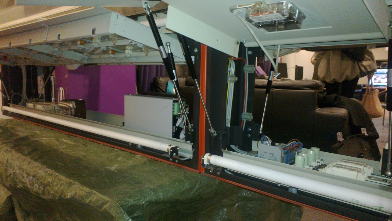
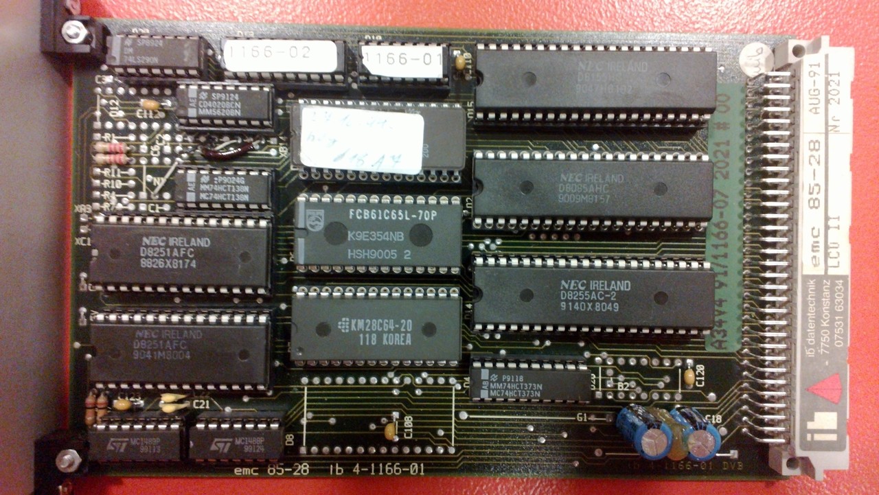
Inside was power circuitry, lamps, heating elements (for keeping rime off during winter, obviously), gas springs for holding the doors open, and other trivial but pretty neat things. The important ones were the daisy-chained LCD screens (ten for each side), and some kind of control box for them. The box appeared to be an old custom-built small computer, dating back to 1991, according to some stickers.
The interesting things in the computer were: an 8085 CPU (Intel 8080-based, mostly), some E(E)PROM, RAM and a peripheral I/O chip, and a couple of UARTs. The UV-erasable EPROM chip had 32 KB of program memory, and one 8 KB EEPROM contained some familiar text strings about the train destinations. The contents of those were pretty easy to dump with a simple proxy program on an AVR that just looped through the memory addresses and printed their contents to serial port.
While studying the machine code with several friends (special thanks to Tuomas "Dezgeg" Tynkkynen) and tools (text editors and IDA, mostly), I heard that Helsinki Hacklab, a nearby hackerspace, had also acquired one display. With them, we got some clue about the actual lcd bus, some components' configurations, and the other card that was in the control box - a modem. Apparently all displays of one station were connected to a single modem-like bus running at 600 baud. Each has a distinct address, configurable with dip switches. We also found out the memory map of the cpu, the speed of the UART chips, and such. A better look at the bootup sequences in a debug mode (also turned on with one of the dip switches), reversed schematics of adapter pcbs (buffer chip, NAND, jumpers, and connectors) at the end of the lcd cables that divide the signal to upper and lower parts of the modules, and some logic analyser like software on an Arduino gave us some more insight that led us forward in parsing the original program.
The assembly code was structured in two parts: one was clearly a hand-written part, dealing with time-critical things like watchdogs, serial communication, and the display bus; the other was some gibberish that was clearly compiled from a higher-level language. It presumably dealt with the actual rendering of the font bits and handing them to the lower-level functions.
L407E:
        lxi     h,00002H
        dad     sp
        mov     e,m
        inx     h
        mov     d,m
        mvi     c,008H
L4087:
        mov     a,e
        ani     001H
        out     042H
        mov     a,e
        rar
        mov     e,a
        call    L4032
        dcr     c
        jnz     L4087
        mvi     c,004H
L4098:
        mov     a,d
        ani     001H
        out     042H
        mov     a,d
        rar
        mov     d,a
        call    L4032
        dcr     c
        jnz     L4098
        ret
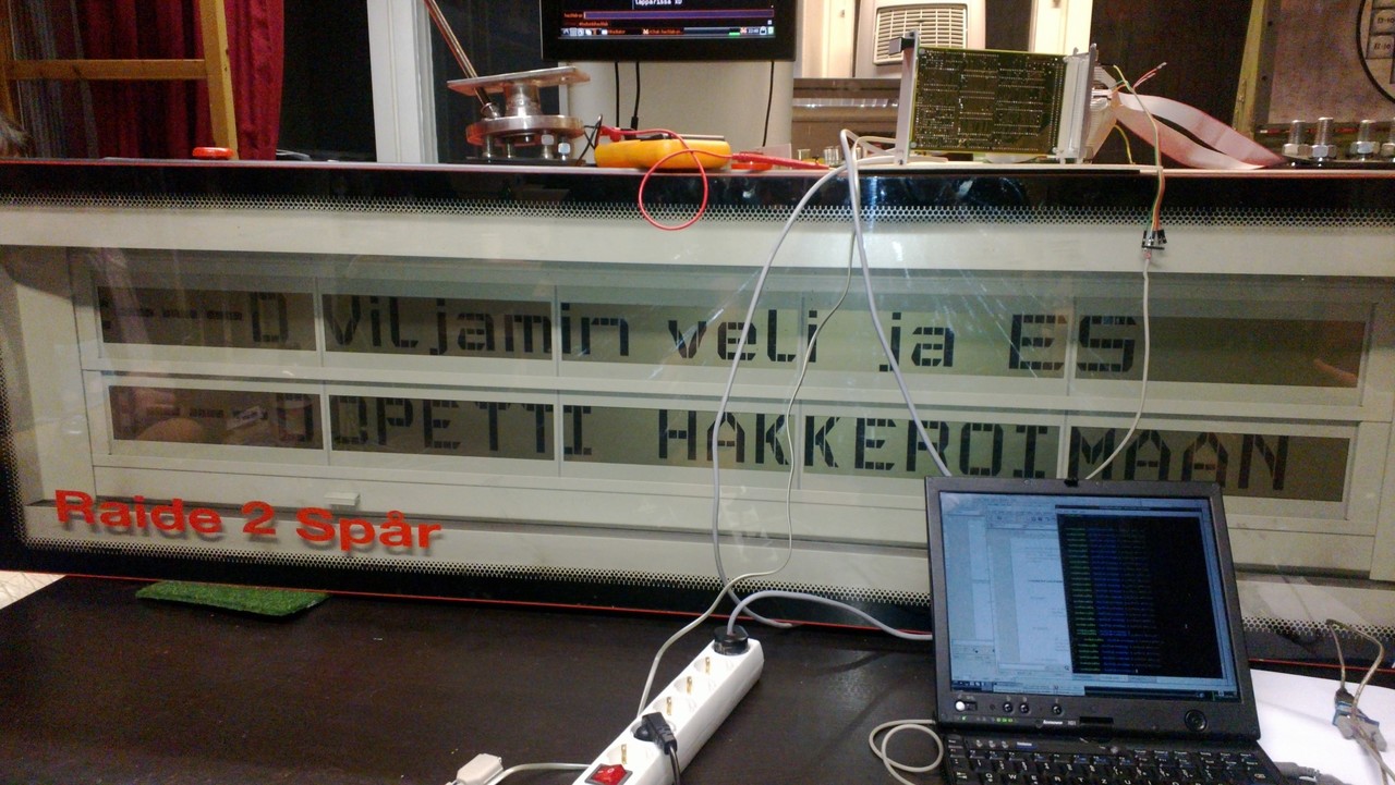
The most important thing would be to control the displays without the original computer, but to get started, the string parsing of the modem protocol was also (mostly) reversed. A simple python script talking to serial port, some wires to correct places (with the help of datasheets, some insight and a multimeter), and setting the address switches to zero got us going, and we got some custom text to the display. The protocol and/or the control software aren't very robust, and some messages need to be repeated because they wouldn't work all the time. The display (consisting of ten smaller modules) is divided in three parts: one 4-module row for the destination name in Finnish, another for the same in Swedish, and just one module on top of another for remaining minutes and the length of the next train. This is the same for both sides, but they could be set to separate addresses with a jumper in the adapter boards.
Finally, the all actual locations of the writes to the chip that is connected to the bus were understood (just a few bits! this bus must be simple). We'd still need the pixel ordering and stuff like that to get custom graphics. Static analysis (i.e. reading the code manually) of the font rendering was just too painful, so the best decision was to find an emulator for 8085 chips with the ability to dump memory writes and run this in it. By carefully parsing the captured bits and looking at closeup photos of the display, the actual format of the bus was found. The bus is practically SPI; one data line and separate clocks for upper and lower parts of each lcd module. The modules consist of 24 colums and 8 rows each, but each column actually has 23 (12 + 11 for upper and lower drivers respectively) separate pixels, more or less triangles. There are also a few address lines for latching the double-buffered pixels in when the whole bit string has been transmitted for a specific set of modules.

After a good deal of hacking and staring at bits and the bootup text again, all the actual physical locations of the pins and also the font map were deciphered. And lots of nasty padding bits in between that seem to make no sense at all - you wouldn't want to see my final code that eats nicely ordered bytes and outputs the displayed bits and padding bits at correct positions. Maybe the displays are controlled by some generic shift register based ICs that have only some pins connected. Those cannot be seen, though - they're somewhere inside the lcd panels and probably cannot be found without breaking them.
As already found in the schematics of the adapters that connect the big ribbon cables to upper and lower portions of the modules, there is a select line for each of the three module groups, and also one for choosing the front or back side. These are ultimately connected to extra i/o pins on the RAM chip, and driven directly by software. It was quite easy to see the correct sequence of these in the emulator capture now that the pin numbers were verified.
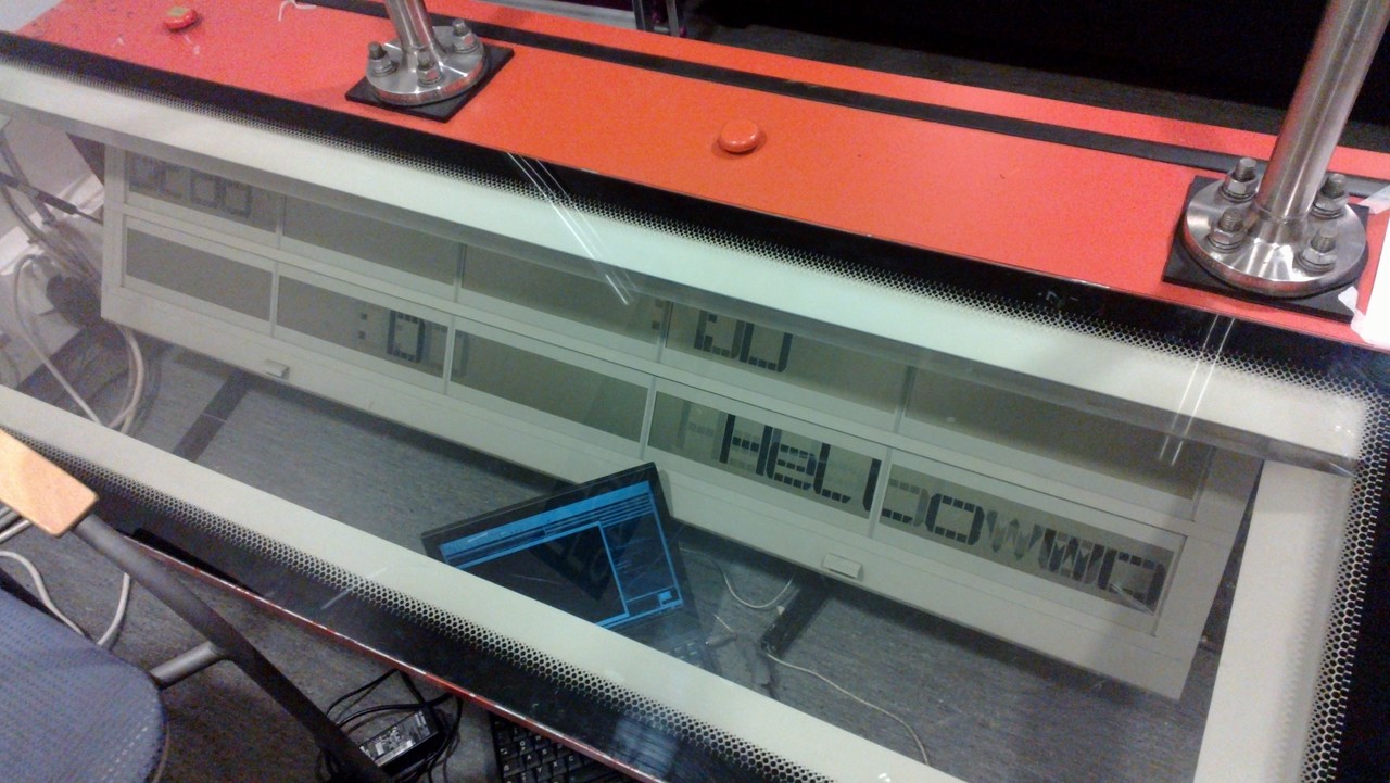
Just one nice evening at the Hacklab for verifying everything, and I had custom code running on Teensy that filled the screen with bit patterns for testing. Now we had the pinout for the actual cables, with supply voltages and all, fully known. Plus the protocol. Next up was a custom font renderer or even a proxy for dumping bits from PC. That was just coding, no reversing anymore. Trivial, right?
No big obstacles were found during the process; it only was important to patiently keep going and have clear milestones on the way. Very important was also documenting everything after every hack session, otherwise lots of minor details would have been forgotten. Later, I wrote some more code to actually draw some meaningful text and graphics. The hardware isn't always available when coding, so I wrote also a display simulator that would show the graphics about the same way as the actual display, and also a simple inverse tool to draw graphics with a mouse and dump the bits in the same format. With those, I was successful enough to write a snake game for it, when Hacklab had a desk in a hobby fair later.
Then, after being too lazy for a long time, I hacked quickly together an independent platform that could be attached directly to the ribbon cables and didn't use the original controller at all. The original box feeds 5 and 7 volts and also a 75 Hz square wave at 5 V to it, in addition to the data lines. With Teensy and some jumpers and stuff on a breadboard and a few sleepless nights in a hurry, I created a really lousy demo that surprisingly won the wild compo at Assembly. The demo uses audio samples from an audio box also found in one of the displays, reversed in quite the same way as the actual displays too, but that's another story.
5 kommenttia
- jalmari 20.08.2013 11:11hyvä saucee! kyllä metronäytöllä heruu.
- dutchclimber 20.08.2013 11:21Thanks for translating.... interesting read!
- Exitium 20.08.2013 14:01sooda <333333333333333
- NusNus 20.08.2013 17:48Tosi mahtava projekti! Jos ois tienny ois hakenu tämmösen koristamaan kotia.
- Thasan 28.08.2014 23:48Kyllä nyt tuommosen näytön takia olisi lähes 400km ajanut suuntaansa hakemaan jos olisi tiennyt.
Oma kommenttisi
Mielipide tämän sivun asiasta? Kirjoita toki. Älä raapusta kuitenkaan ihan asiattomia juttuja.
Jos on yksityisempää asiaa, tarkkaa kysyttävää tai aihetta pidemmälle keskustelulle, käytä yhteydenottolomaketta kommentoinnin sijaan.
Hölmöt kommentit saatetaan moderoida pois jälkikäteen.